Page 1 of 1

HBP Wiring

Posted: Wed Apr 01, 2015 10:25 pm
by rpollack
We are working on an improvement to the HBP wiring. We are considering fastening a card edge connector to the bottom rear edge of the HBP. Then the harness will just connect directly to the edge connector. I am just checking to see if you have any ideas or suggestions on this topic.

Thanks,
Rick

Re: HBP Wiring

Posted: Thu Apr 02, 2015 1:34 am
by ednisley
rpollack wrote:fastening a card edge connector to the bottom rear edge of the HBP.
The flying cable from chassis to HBP must have strain relief on the outboard side of the new connector, which I think puts way too much stress on the back end of the spring-supported HBP: dynamic forces applied to the the HBP change the platform Z position as a function of travel along the Y axis. Those platform springs are the weakest point of the whole design.

I'd much rather see a pigtail from the HBP to a connector mounted firmly on the Y-axis slide (below the springs), so that the pigtail doesn't move in relation to the HBP. Then you can do a good job of strain relief on the flying cable-to-connector joint, without affecting the HBP.

I ran a strut out the back of the Y-axis stage in a truly hideous hack:
http://softsolder.com/2013/07/05/makerg ... ilization/

Image

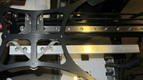
Then lashed the HBP cable to that strut:
Image

That's not as good as a pigtail with a firmly mounted connector, but it was a start.

I've since switched to a different HBP with longer wires running directly to the chassis that reduce the acute bending. It's not nearly as good-looking as the loom, though.

A pair of Anderson Powerpoles would be a much more reliable choice than any PCB edge connector, because the copper PCB traces will fret against the contacts after repeated mechanical motion. If you must clamp the connector together anyway, you may as well use a high-current latching connector and be done with it.

PCB-mount Powerpoles exist:

http://www.andersonpower.com/products/p ... rpole.html

But that PCB should be attached to the Y-axis slide, so it's not clear they're an advantage over ordinary Powerpoles on a pigtail.

Re: HBP Wiring

Posted: Thu Apr 02, 2015 3:11 am
by rpollack
Thank you, Ed.

Re: HBP Wiring

Posted: Thu Apr 02, 2015 4:12 am
by insta
rpollack wrote:We are working on an improvement to the HBP wiring. We are considering fastening a card edge connector to the bottom rear edge of the HBP. Then the harness will just connect directly to the edge connector. I am just checking to see if you have any ideas or suggestions on this topic.

Thanks,
Rick
A combination of Ed's idea with the splint, and a cable chain to make use of that nice, expensive automation cable you're using for the heated bed. The cable chain could be attached to the Z stage off to the side (so it collides with the electronics, hmm...) anchored by the Y motor and a printed/molded/metal part to hold the final bend from the chain to the HBP split steady.

Re: HBP Wiring

Posted: Wed Apr 08, 2015 7:24 pm
by BigBadBry
This is what I did to safeguard my own wire connection. It might be nice to have it direct the wire more to the rear as opposed to the side, but the general approach seems to be easy to implement.. Another member posted a similar solution using a conduit clamp, which might be even more effective.

https://www.dropbox.com/s/d4k9wgrww6sts ... 0.jpg?dl=0

Re: HBP Wiring

Posted: Wed Apr 08, 2015 9:18 pm
by Dale Reed
insta wrote:A combination of Ed's idea with the splint, and a cable chain to make use of that nice, expensive automation cable you're using for the heated bed. The cable chain could be attached to the Z stage off to the side (so it collides with the electronics, hmm...) anchored by the Y motor and a printed/molded/metal part to hold the final bend from the chain to the HBP split steady.
Rick, I'm pretty sure you're aware of jimc's arrangement, where the wires come off toward the inboard side, rather than straight out the back. I do like the idea of cable-track for the flexing wires. Perhaps anchor it next to the Y motor somehow. I bought about a meter each of three or four sizes of black cable-track (from Amazon) and haven't gotten a chance to dink with them -- sitting in a box next to the desk with the M2. You're welcome to have some -- I can stop by the shop any day at lunchtime (except Friday this week). I can show you or Josh what I had in mind...

Dale

Re: HBP Wiring

Posted: Sun May 10, 2015 12:34 am
by Slipshine
I just did a quick fix that seemed to work out for me.

On the plug I put a stiff piece of heat shrink tubing to take the stress off the solder joint.

On the Heated build platform I loosely zip tied the cable bundle to the plate clamp.
0509151619.jpg
0509151619.jpg (87.89 KiB) Viewed 10754 times
0509151619a.jpg
0509151619a.jpg (49.7 KiB) Viewed 10754 times
Hope this helps .

It can serve as a quick fix in the field until something new is adopted.

you could use electrical tape if you didn't have the heat shrink tubing.