Hey all,
I'm trying to power a camera stabilizer gimbal that has a working voltage of 7.4 - 14.8 volts with a 16.8 volt battery. (4S lipo, 5300mAh, 35C)
The working current of this gimbal is 200mA - 500mA.
I figured that I would make a voltage divider using 2 resistors. a 220 ohm and a 470 ohm. That would take the 16.8 volts down to 11.4
When I tried this, I got 11.4 volts on my meter! Success! When I plugged in the component, It failed to start up! FAIL! (red solid LED - manual says error)
Is there something I'm missing?
Voltage divider - What am I doing wrong.
-
JohnnyRobot

- Posts: 128
- Joined: Tue Apr 22, 2014 9:25 pm
Voltage divider - What am I doing wrong.
╒═════════════════════════════════════════════════════════╕
-- Hi! No signature here.
╘═════════════════════════════════════════════════════════╛
-- Hi! No signature here.
╘═════════════════════════════════════════════════════════╛

Re: Voltage divider - What am I doing wrong.
The voltage divider only works if there is no other current going in or out of the point between the resistors. In this case, you are drawing 200 to 500mA off of that point, which invalidates the voltage divider.
Your best choice is to get a variable output voltage regulator---that's basically just a voltage divider followed by an op amp, so the op amp follows the voltage on the voltage divider without drawing any current off of it, so the voltage divider remains valid.
The other choice is that you can make your load part of the voltage divider. Although the load can change from 200 to 500mA, the voltage can vary from 7.4 to 14.8, so you might be able to pull it off, assuming the gimbal works reasonably consistently over that range.
-
JohnnyRobot
- Posts: 128
- Joined: Tue Apr 22, 2014 9:25 pm
Re: Voltage divider - What am I doing wrong.
Thanks Tim.
I had a suspicion that factored into the equation. I've noticed that the gimbal performs well as long as the voltage remains between 9 and 13 volts. Outside of that, the gains get screwy. (In my opinion)
I like the 3rd option because I have a whole box of various resistors and I don't need to buy anything
Unfortunately, I don't even know were to begin including the load into the voltage divider. Wikipedia here I come.
╒═════════════════════════════════════════════════════════╕
-- Hi! No signature here.
╘═════════════════════════════════════════════════════════╛
-- Hi! No signature here.
╘═════════════════════════════════════════════════════════╛
Re: Voltage divider - What am I doing wrong.
You would be better off going the voltage regulator route, because.....
You could measure the current in the motor winding at 9 volts and the current in the motor winding at 13 volts. That would give you the range of current values which would allow you to pick a resistor ladder that might do the trick, except....
The motor will draw more current when loaded. More load = more current.
You would have to take that into account when you set up your voltage divider.
So, you would be better off with the voltage regulator solution. Just make sure the regulator can handle the current.
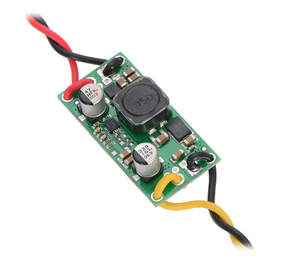
Edit: You could use this https://www.pololu.com/product/2572.
It has an input voltage range of 3-30 volts, adjustable output voltage 4 - 12 volts, at about 2 amps when the input voltage is close to the output voltage. De-rate current output as the voltages become significantly different (graph on the web site) and is about $15.
2nd Edit:
I just re-read the thread and noticed that you are using Li-Po batteries as your power source. If you use the recommendation above you would have to be careful as the regulator mentioned is a buck/boost type regulator and it would deplete your battery to an unsafe level if you let it run long enough.
Or, just use an LM317
You could measure the current in the motor winding at 9 volts and the current in the motor winding at 13 volts. That would give you the range of current values which would allow you to pick a resistor ladder that might do the trick, except....
The motor will draw more current when loaded. More load = more current.
You would have to take that into account when you set up your voltage divider.
So, you would be better off with the voltage regulator solution. Just make sure the regulator can handle the current.
Edit: You could use this https://www.pololu.com/product/2572.
It has an input voltage range of 3-30 volts, adjustable output voltage 4 - 12 volts, at about 2 amps when the input voltage is close to the output voltage. De-rate current output as the voltages become significantly different (graph on the web site) and is about $15.
2nd Edit:
I just re-read the thread and noticed that you are using Li-Po batteries as your power source. If you use the recommendation above you would have to be careful as the regulator mentioned is a buck/boost type regulator and it would deplete your battery to an unsafe level if you let it run long enough.
Or, just use an LM317

Re: Voltage divider - What am I doing wrong.
If the pack has a built-in protection circuit, that should disable the output when the battery voltage hits the lower limit.lem wrote:it would deplete your battery to an unsafe level
If it's a bare-cell pack, all bets are off...

Re: Voltage divider - What am I doing wrong.
LM317's gonna be really hard to keep cool ... you're on a much better track with the Pololu part.lem wrote:You would be better off going the voltage regulator route, because.....
You could measure the current in the motor winding at 9 volts and the current in the motor winding at 13 volts. That would give you the range of current values which would allow you to pick a resistor ladder that might do the trick, except....
The motor will draw more current when loaded. More load = more current.
You would have to take that into account when you set up your voltage divider.
So, you would be better off with the voltage regulator solution. Just make sure the regulator can handle the current.
Edit: You could use this https://www.pololu.com/product/2572.
It has an input voltage range of 3-30 volts, adjustable output voltage 4 - 12 volts, at about 2 amps when the input voltage is close to the output voltage. De-rate current output as the voltages become significantly different (graph on the web site) and is about $15.
2nd Edit:
I just re-read the thread and noticed that you are using Li-Po batteries as your power source. If you use the recommendation above you would have to be careful as the regulator mentioned is a buck/boost type regulator and it would deplete your battery to an unsafe level if you let it run long enough.
Or, just use an LM317
Johnny, I don't suppose you could just put a second 2S 500mah pack on there? It'll weigh 80 grams and run you $5, and substantially outlast the battery flying the quad/hex the gimbal is mounted on.
Custom 3D printing for you or your business -- quote [at] pingring.org
-
JohnnyRobot
- Posts: 128
- Joined: Tue Apr 22, 2014 9:25 pm
Re: Voltage divider - What am I doing wrong.
I've thought about adding a second battery. The problem is, it's a tricopter and I'm very close to my motor/ESC weight limit.
I picked up an LM317 because it was cheap. I haven't had time to test it out yet. I think I'm going to go with the Pololu regulator for the long term.
I'm not worried about it draining my battery to unsafe levels because it's only powered when the tricopter is plugged in, and I'll be monitoring the battery level from my ground station.
Also, I like this:
If it doesn't work for this application, it seems like a handy gadget to have for future projects.
╒═════════════════════════════════════════════════════════╕
-- Hi! No signature here.
╘═════════════════════════════════════════════════════════╛
-- Hi! No signature here.
╘═════════════════════════════════════════════════════════╛
Re: Voltage divider - What am I doing wrong.
You're going to be dissipating about 2.5 watts across that LM317 -- you need a larger heatsink than you think you do, at least one the size of your thumb. Try and get it into the propwash, too.
Custom 3D printing for you or your business -- quote [at] pingring.org
Re: Voltage divider - What am I doing wrong.
Saw these recently: a DC-to-DC converter that has the same lead spacing as a TO-220 form voltage regulator (e.g., LM7812). Since it's a DC-to-DC converter, it doesn't dissipate as much heat as a linear voltage regulator (which basically dissipates (16 minus 12 volts) time (0.5 amps) -- thus 2 watts or more). 16 volts in, 12 volts out, 0.5 A max current seems to fit what you are doing perfectly. Tiny package, little heat dissipation, way more efficient (less input current required for the given output equals less power in equals lower electric bill or longer battery life).
http://www.recom-international.com/pdf/ ... xx-0.5.pdf
Hope this helps!
Dale
http://www.recom-international.com/pdf/ ... xx-0.5.pdf
Hope this helps!
Dale