Wondering if anyone can tell me what is causing this. I have gone through the extrusion calibration square etc amd dialed in for 40 EW,
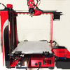
This is printed in PET+ and you can see from the picture that the rest of the outside is pristine, it just seems to happen when performing small curves .
It tends to ruin what otherwise are amazing prints
Gaps between lines
Gaps between lines
- Attachments
-
- IMG_20150227_224206-scaled.jpg (461.27 KiB) Viewed 9318 times
Re: Gaps between lines
Post your fff settigs file. What slicer are you using? That is the perimeters stepping over in a more horizontal area. keep in mind those are perimeters so if you dont have enough of them then youll see through it.

Re: Gaps between lines
And only on the top surface, which is the clue.Bratag wrote:when performing small curves
Those surfaces are very shallow domes or saddles, so the change in height within the thickness of a single thread covers a large XY area: the printer's limited Z resolution replaces the object's smooth curve with a flat layer.
The gaps in the top layer expose the interior of the object, which means they don't have firm support. That means the threads stretch over the gaps between the support structure (aka infill) and turn into narrow rods, rather than flattened rectangles, and that produces gaps between adjacent threads in what should be a flat surface with solid fill.
If you increase the number of layers in the top surface to three or four (or more!), then the visible outer layer will have continuous support underneath: the threads will have the proper width and the gaps should disappear.
You could increase the infill density, but that would increase the printing time without much benefit.
You could modify the infill or top surface parameters in just the section with those surfaces, so the rest would print as-is. Slic3r can now do that, although I haven't tried it, and S3D apparently can, too.
It's definitely a crisis of rising expectations, isn't it? [grin]
Re: Gaps between lines
Ed, thanks for the explanation. I guess what I find most interesting is that it seems to treat some of the model as a top layer and some not. Not visible in the picture are gums and teeth that all have small curves but were treated as an outside top surface and given 3 layers (as per my config). These gapped areas are given only one.
I am including my FFF here which is based off of the one that I think jimc posted in some random thread. Looking at it now I may see the problem with the thin wall behavior setting. It is set t 25% where on my PLA configs its 10
I am including my FFF here which is based off of the one that I think jimc posted in some random thread. Looking at it now I may see the problem with the thin wall behavior setting. It is set t 25% where on my PLA configs its 10
- Attachments
-
- Makergear-PET+White.zip
- (2.65 KiB) Downloaded 578 times
Re: Gaps between lines
top surfaces are 0 deg only. perfectly horizontal. anything other than that the angle is made by the perimeters. when the slicer steps over to make another line on a steep angle the will be a gap but depending on how many perimeters you have set the gap may be filled with perimeters or it may be a top surface. if you slice your part again make changes on the number of top surfaces and perimeters. keep changing the values and look closely at the preview you will see what it happening.
Re: Gaps between lines
I expected that the top infill would extend downward from the uppermost layer, even for those nearly horizontal "walls", but apparently that's not happening.Bratag wrote:These gapped areas are given only one.
Slic3r has an "add more perimeters if needed" setting to cover that situation and perhaps S3D has something similar. It's supposed to detect nearly horizontal surfaces and add enough perimeters to fill the openings, but I don't know whether it will also add enough infill to support those additional threads.
For obvious reasons, you don't want to have a dozen perimeters throughout the entire model. Perhaps you can use a modification region to tweak the settings for just those upper surfaces.